


Files
Download Full Text (852 KB)
Description
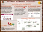
Andrew Walkowski, Daniel Breloff and Joshua Evans, ENT 466: Electrical Design II
Faculty Mentor: Professor Leonard Fiume, Engineering Technology
This project will solve the dual problem of speed control and motor protection of an unloaded operating Induction motor. A Variable Frequency Drive or (VFD) is used to provide 3-phase AC power to a 1 HP motor. A graphical user interface (GUI) written in the LabVIEW programming language will control the motor speed and direction, as well as monitor the voltage, current, temperature, and actual RPM of the motor shaft. A national instruments Data Acquisition Device or (DAQ) will measure all real-world signals previously mentioned. Four main components comprise this system. First is a VFD enclosure that receives a single-phase input power and outputs 3-phase power to the next enclosure. The Voltage/Current measurement enclosure then uses high-voltage and high-current transducers to measure the VFD output power, converts these signals into a lower voltage to be measured by the DAQ, and passes through the high voltage and high current into the motor. The third enclosure contains the DAQ device, the temperature measurement circuit, the RPM feedback measurement circuit, and four solid state relays and receives the low voltage signals from the Voltage/Current measurement enclosure. The solid-state relays in the DAQ enclosure take program commands to the VFD enclosure to determine motor RUN/STOP and FWD/REV operation. The last component is the Induction motor itself. The RPM feedback circuit is the critical component to allow for a Proportional, Integral and Derivative (PID) control of motor speed. This circuit will accurately measure the motor shaft rotation speed and feed a proportional DC voltage signal into the DAQ, as the program incorporates the signal into its PID loop and varies the analog output voltage from the DAQ device into the VFD to set the user defined speed in HZ. Accurate real-time data from all signals will be displayed and recorded in the GUI to ensure proper system operation. Five failure modes will be monitored by the LabVIEW program. Preset values and control logic from the GUI and solid state relays will disable the output of the VFD should any of the failure modes occur.
Publication Date
2020
Disciplines
Computer Sciences | Engineering
Recommended Citation
Walkowski, Andrew; Breloff, Daniel; and Evans, Joshua, "Closed-Loop Speed Control and Protection Circuit for an AC Induction Motor" (2020). Computer Information Systems and Engineering Technology. 22nd Annual Student Research and Creativity Conference. SUNY Buffalo State.
https://digitalcommons.buffalostate.edu/srcc-sp20-compeng/22